Flashing OpenIPC on the Anpiz IPC-D3B53W-S

The Anpiz IPC-D3B53W-S is a cheap Amazon dome camera that turns out to be a surprisingly capable piece of hardware once you replace the stock firmware with OpenIPC. Under the hood it runs a SigmaStar SSC377 (infinity6c) SoC with a SC4336P image sensor, capable of 2560×1440 at 30fps. Here’s everything you need to get it running.


What You’ll Need

  • Anpiz IPC-D3B53W-S camera
  • CH341A programmer and a flash chip clamp (SOIC-8)
  • A PC with flashrom installed
  • OpenIPC 16MB Lite image for SSC377 — download from openipc.org
  • SSH client and a network cable

Step 1 — Flash the Firmware

The camera uses a GD25Q128C 16MB SPI NOR flash chip on the PCB. You do not need to desolder it — a SOIC-8 chip clamp works fine.

  1. Disassemble the camera and locate the flash chip on the main board
  2. Clip the CH341A clamp onto the chip (power the camera off first)
  3. Connect the CH341A to your PC and flash the OpenIPC image:
flashrom -p ch341a_spi -w openipc-ssc377-lite-16mb.bin
  1. Verify the write completes without errors
  2. Remove the clamp, reassemble, and power the camera on

The camera should come up on your network via DHCP within about 30 seconds. Set a root password in the Web UI, then ssh in as root.


Step 2 — Copy the IQ Tuning File

The stock firmware ships with a sensor-specific image quality binary (sc4336p_day.bin) that contains the color correction matrix, white balance tables, and gamma curves tuned for this exact sensor. Without it, colors look washed out and flat.

Extract the file from the original firmware (or download my copy here) and copy it to the camera. The easiest method if you only have SSH access (no SCP) is base64:

On your PC:

base64 sc4336p_day.bin

On the camera via SSH:

base64 -d > /etc/sensors/sc4336p.bin << 'EOF'
<paste base64 output here>
EOF

# Verify the file size (should be 111620 bytes)
wc -c /etc/sensors/sc4336p.bin

Then tell majestic to use it in /etc/majestic.yaml:

isp:
  iqFile: /etc/sensors/sc4336p.bin

Step 3 — Fix the CMA Memory Allocation

Out of the box, OpenIPC only reserves 2MB of CMA memory for the video encoder. The SC4336P at 1920×1080 needs at least 6.2MB, which causes the encoder to fail silently and produce a solid pink image.

Increase the CMA reservation in the boot environment:

fw_setenv bootargs "console=ttyS0,115200 panic=20 root=/dev/mtdblock3 init=/init mtdparts=NOR_FLASH:256k(boot),64k(env),2048k(kernel),5120k(rootfs),-(rootfs_data) LX_MEM=0x4000000 mma_heap=mma_heap_name0,miu=0,sz=0x2000000 cma=8M"

Reboot and verify:

cat /proc/meminfo | grep -i cma
# CmaTotal: 8192 kB

Step 4 — Configure the GPIO Pins (IR Filter and Light)

This was the most involved part of the setup. The stock firmware doesn’t document its GPIO assignments anywhere obvious, so finding the right pins required extracting and analysing the firmware.

The key was finding ko.sh — the kernel module startup script embedded in the squashfs of the original firmware — which explicitly exports and tests the ICR motor pins at boot.

The complete pin map for this camera:

FunctionInterfacePin/Channel
ICR filter — day coilGPIO11
ICR filter — night coilGPIO80
LED lightGPIO13
IR LED (infrared light)PWMpwmchip0/pwm4
White lightPWMpwmchip0/pwm0
Light sensor inputGPIO23 (input)
Alarm inputGPIO44 (input)
Alarm outputGPIO61 (output)

The IR cut filter is a mechanical two-coil motor — it needs a brief pulse (~250ms) on one pin to switch to night position and a pulse on the other to return to day. Both pins sit at 0 between switches. The IR and white lights are PWM-controlled at a 50kHz period, not simple GPIO on/off.

Add the ICR pins to /etc/majestic.yaml:

nightMode:
  irCutPin1: 11
  irCutPin2: 80
  irCutSingleInvert: false
  lightMonitor: false # doesn't seem to work
  lightSensorInvert: false
  backlightPin: 13

To manually test the filter from the shell:

# Switch to day mode
echo 1 > /sys/class/gpio/gpio80/value
echo 0 > /sys/class/gpio/gpio11/value
usleep 250000
echo 0 > /sys/class/gpio/gpio11/value
echo 0 > /sys/class/gpio/gpio80/value

# Switch to night mode
echo 1 > /sys/class/gpio/gpio11/value
echo 0 > /sys/class/gpio/gpio80/value
usleep 250000
echo 0 > /sys/class/gpio/gpio11/value
echo 0 > /sys/class/gpio/gpio80/value

You should hear a faint click each time as the filter moves.


The Pink Screen Mystery

During setup we ran into a solid pink image with no visible picture at all. It turned out to be two separate issues that happened to occur at the same time:

  1. CMA too small — the encoder was failing silently (fixed by the cma=8M bootarg above)
  2. Lens not fully seated — the lens barrel wasn’t screwed down flush to the sensor PCB, letting ambient light bleed in through the gap from behind and saturating the sensor pink

If you see a solid pink image, check both. The CMA fix is in the bootargs. The lens issue is mechanical — just unscrew the dome cover and tighten the lens down until it’s flush.


Step 5 — Automatic Day/Night Switching

OpenIPC’s built-in night mode appears to have a significant limitation on this camera: enabling lightMonitor: true (which uses image brightness to decide when to switch) disables all the night mode buttons in the web UI. And setting lightMonitor: false to get the buttons back means automatic switching stops working for some reason. You can’t have both at the same time. I hope I am wrong – if so, correct me!

But my workaround is to disable lightMonitor and handle automatic switching yourself with a cron script that uses sunrise/sunset times for your location. Save the following to /root/nightwatch.sh:

#!/bin/sh

LAT=40.0000
LON=-85.0000
STATE_FILE=/tmp/nightmode_state
CACHE=/tmp/sun_times

set_day() {
    if [ "$(cat $STATE_FILE 2>/dev/null)" != "day" ]; then
        echo "Switching to DAY mode"
        curl -s "http://localhost/night?enabled=0" > /dev/null
        echo 11 > /sys/class/gpio/export 2>/dev/null
        echo 80 > /sys/class/gpio/export 2>/dev/null
        echo out > /sys/class/gpio/gpio11/direction 2>/dev/null
        echo out > /sys/class/gpio/gpio80/direction 2>/dev/null
        echo 1 > /sys/class/gpio/gpio80/value
        echo 0 > /sys/class/gpio/gpio11/value
        usleep 250000
        echo 0 > /sys/class/gpio/gpio11/value
        echo 0 > /sys/class/gpio/gpio80/value
        echo day > $STATE_FILE
    else
        echo "Already in DAY mode"
    fi
}

set_night() {
    if [ "$(cat $STATE_FILE 2>/dev/null)" != "night" ]; then
        echo "Switching to NIGHT mode"
        curl -s "http://localhost/night?enabled=1" > /dev/null
        echo 11 > /sys/class/gpio/export 2>/dev/null
        echo 80 > /sys/class/gpio/export 2>/dev/null
        echo out > /sys/class/gpio/gpio11/direction 2>/dev/null
        echo out > /sys/class/gpio/gpio80/direction 2>/dev/null
        echo 1 > /sys/class/gpio/gpio11/value
        echo 0 > /sys/class/gpio/gpio80/value
        usleep 250000
        echo 0 > /sys/class/gpio/gpio11/value
        echo 0 > /sys/class/gpio/gpio80/value
        echo night > $STATE_FILE
    else
        echo "Already in NIGHT mode"
    fi
}

iso_to_ts() {
    DT=$(echo $1 | sed 's/T/ /' | sed 's/+[0-9:]*$//' | sed 's/-[0-9][0-9]:[0-9][0-9]$//')
    date -u -d "$DT" +%s
}

is_valid_ts() {
    [ -n "$1" ] && echo "$1" | grep -q '^[0-9]*$'
}

CACHE_AGE=0
if [ -f $CACHE ]; then
    CACHE_AGE=$(( $(date +%s) - $(date -r $CACHE +%s 2>/dev/null || echo 0) ))
fi

FORCE_FETCH=0
if [ ! -f $CACHE ] || [ $CACHE_AGE -gt 86400 ]; then
    FORCE_FETCH=1
else
    read SUNRISE_TS SUNSET_TS < $CACHE
    if ! is_valid_ts "$SUNRISE_TS" || ! is_valid_ts "$SUNSET_TS"; then
        echo "Bad cache detected, clearing"
        rm -f $CACHE
        FORCE_FETCH=1
    else
        echo "Cached: sunrise=$SUNRISE_TS sunset=$SUNSET_TS"
    fi
fi

if [ "$FORCE_FETCH" = "1" ]; then
    echo "Fetching sun times from API"
    RESPONSE=$(curl -s "https://api.sunrise-sunset.org/json?lat=$LAT&lng=$LON&formatted=0")
    SUNRISE=$(echo $RESPONSE | grep -o '"sunrise":"[^"]*"' | cut -d'"' -f4)
    SUNSET=$(echo $RESPONSE | grep -o '"sunset":"[^"]*"' | cut -d'"' -f4)
    SUNRISE_TS=$(iso_to_ts "$SUNRISE")
    SUNSET_TS=$(iso_to_ts "$SUNSET")
    if is_valid_ts "$SUNRISE_TS" && is_valid_ts "$SUNSET_TS"; then
        echo "$SUNRISE_TS $SUNSET_TS" > $CACHE
        echo "Fetched: sunrise=$SUNRISE_TS sunset=$SUNSET_TS"
    else
        echo "Failed to fetch valid sun times, defaulting to night"
        set_night
        exit 1
    fi
fi

NOW=$(date +%s)
echo "Now=$NOW sunrise=$SUNRISE_TS sunset=$SUNSET_TS"

if [ "$NOW" -ge "$SUNRISE_TS" ] && [ "$NOW" -lt "$SUNSET_TS" ]; then
    set_day
else
    set_night
fi

Update LAT and LON for your location. Make it executable and add it to cron:

chmod +x /root/nightwatch.sh
echo "*/5 * * * * /root/nightwatch.sh >> /tmp/nightwatch.log 2>&1" >> /etc/crontabs/root
killall crond 2>/dev/null
crond

The script caches sunrise/sunset times for 24 hours (using the free sunrise-sunset.org API), only pulses the ICR motor when the state actually needs to change, and fails safely to night mode if the API is unreachable.

With this approach, set lightMonitor: false in majestic.yaml so the web UI buttons remain functional for manual overrides.


Final majestic.yaml

Here’s a working configuration for reference:

system:
  webPort: 80
isp:
  iqFile: /etc/sensors/sc4336p.bin
  antiFlicker: disabled
image:
  mirror: false
  flip: false
  rotate: 0
  contrast: 50
  hue: 50
  saturation: 50
  luminance: 50
video0:
  enabled: true
  codec: h264
  size: 1920x1080
  fps: 20
  bitrate: 4096
  rcMode: vbr
  gopSize: 1
video1:
  enabled: false
nightMode:
  colorToGray: true
  irCutPin1: 11
  irCutPin2: 80
  irCutSingleInvert: false
  lightMonitor: false
  lightSensorInvert: false
  backlightPin: 0
rtsp:
  enabled: true
  port: 554
watchdog:
  enabled: true
  timeout: 300

Summary

The Anpiz IPC-D3B53W-S is a solid candidate for OpenIPC. The hardware is capable, the sensor driver is already supported upstream, and once the IQ file, CMA, and GPIO pins are sorted it runs well. The main gotchas are the CMA allocation (easy fix), finding the correct ICR GPIO pins (GPIO 11 and 80, not obvious without digging into the original firmware), and making sure the lens is properly seated after reassembly.
Bypassing the Dallas DS1991 Key on a Star Trek Voyager Arcade

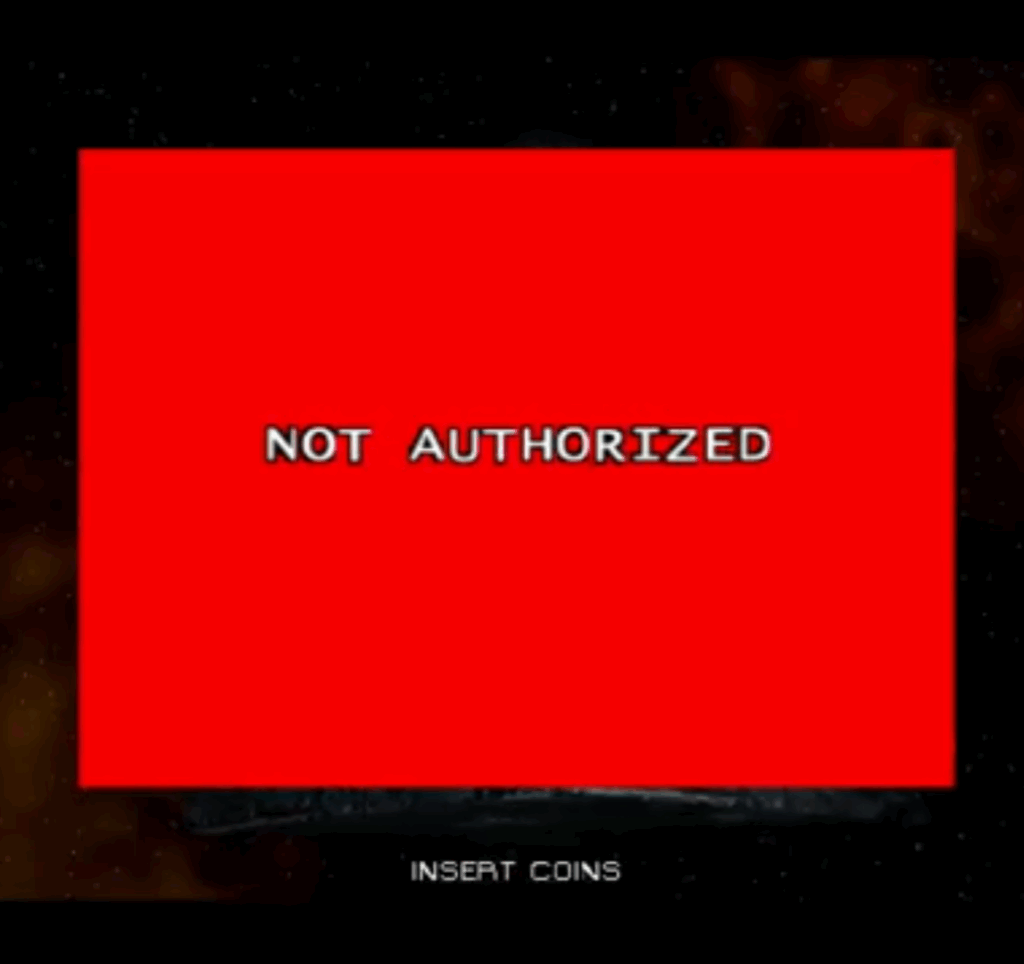
Bringing old arcade machines back to life is part repair, part detective work. My latest project: a Star Trek: Voyager arcade cabinet that refused to boot because of a failed security device—the Dallas DS1991 iButton. With its internal battery long dead and no manufacturer support, the game only showed a bright red “Not Authorized” screen.

Following the Trail

The first clue was right in the binary: the “Not Authorized” string. Cross-referencing it in IDA Pro led me to the code path that displayed the failure message.

I noticed the message was triggered when a DWORD variable, ibok, was set to zero. Tracing it further, I saw that ibok was set by the return value of a function named verify_ib—the routine in charge of checking the iButton.

A Simple Fix

Instead of trying to emulate or repair the dead iButton, I decided to patch the function directly. The logic was straightforward:

  • If verify_ib returned 0 → fail, show red screen.
  • If verify_ib returned 1 → success, boot the game.

So I replaced the body of verify_ib with just two instructions:

mov eax, 1
ret

This forces the function to always succeed, no iButton required.

Back on the Bridge

With the patch applied, the game now boots cleanly and plays perfectly.

Sometimes arcade preservation isn’t about fixing hardware—it’s about understanding the software well enough to get it running again. In this case, a little reverse-engineering brought Voyager back online, ready to defend the Delta Quadrant once more.

Resurrecting a Dead HP ProBook 4540s with a CH341A BIOS Flash

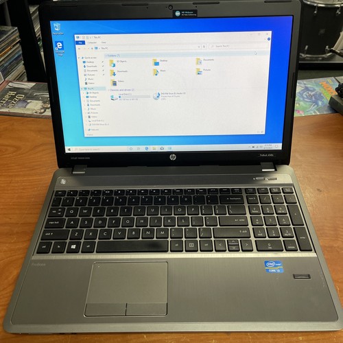
I recently picked up a free HP ProBook 4540s from Facebook Marketplace. It was advertised as non-working — when plugged in, the caps lock light blinked and the fans spun at full speed, but no display, no POST.

First suspect? Bad RAM? I swapped sticks and slots — nothing.

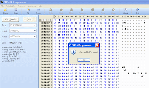
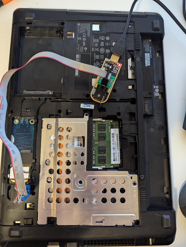
Digging deeper, I found an obscure forum post suggesting BIOS corruption is somewhat common in this model laptop. That led me to discovering a BIOS dump on another site (after plenty of hunting). I used a CH341A programmer and SOIC8 clip to flash the BIOS chip directly. No luck with flashrom (kept hanging), so I busted out my trusty Windows XP VM and the Chinese flashing software.

BIOS Dump is here

After writing the dump and reconnecting the charger… it posted!

Moral of the story: don’t give up on “dead” laptops — sometimes a $5 programmer and a bit of digging can bring them back to life.

Recovering the operator setup PIN on a JVL Encore or Echo

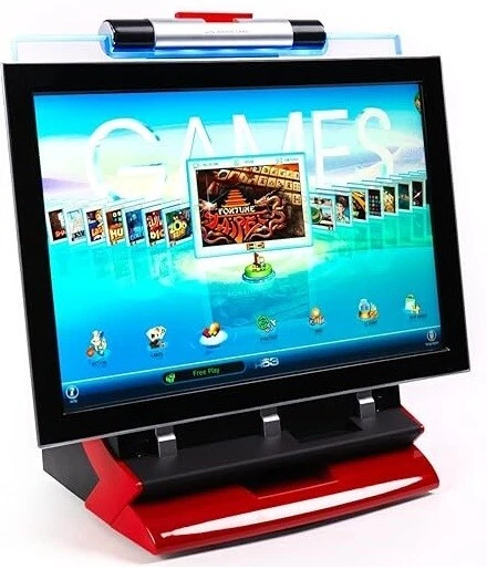
The JVL Echo and Encore are touchscreen arcade machines with 100+ games that used to be found in bars and restaurants. Now they are part of a forgotten era of arcade gaming, largely replaced by cell phones. However, a home collectors market is emerging for those who want to play these machines for their nostalgia.

I recently had a customer bring in his Echo. He purchased it from a vendor, but the operator setup menu was locked with a PIN number that nobody knew. I was tasked with trying to recover and/or reset it. JVL support said the only solution was a new I/O board for $380 which I would then have to pass on to the customer, so I decided to try other means.

Performing a factory reset on the machine made no difference. The PIN number still persisted even after replacing the internal SD card with a fresh installation. I assumed the PIN number must be stored somewhere on the internal I/O board. Looking at the I/O board, I saw an EEPROM which I dumped using a ch341a, but within the dump there was nothing remarkable.

So, I resorted to poking around in the software itself. The JVL software runs on top of a stripped down version of Linux. Having experience already working on these machines, I knew there was a webserver running on port 88 that allowed access to operator setup, but I did not know if that also required a PIN or not. Turns out it does not, and I was able to recover the PIN remotely via my web browser.

Below is the method I used to recover the operator setup PIN:

  1. I obtained a shell by booting into the game and pressing CTRL + ALT + F2 which dropped me to a console.
  2. My original method (easier/better method is below):
    I plugged in an Ethernet cable and set up networking by running ifconfig eth0 10.0.3.5 and confirmed I could ping my router
  3. I navigated my desktop PC web browser to http://10.0.3.5:88/setuphd/machine/standalone/setup/setupsystem.htm which brought up operator setup with no PIN check
  4. I navigated to Access Control and clicked the button “Change Operator’s PIN”. For some reason, I was unable to change the PIN from this screen. The web server appeared to hang and I had to restart the machine. So I decided to focus my efforts on recovering the PIN.
  5. The PIN was prepopulated in the setup but obfuscated like a password, so I resorted to some jQuery. I opened the browser console and entered this code to load the jQuery library:
    var jq = document.createElement('script');
    jq.src = "https://ajax.googleapis.com/ajax/libs/jquery/3.5.1/jquery.min.js";
    document.getElementsByTagName('head')[0].appendChild(jq);
  6. Next, I ran this code to return the value of any password box:
    $('[type=password]').val();
    which yielded output
    '2233'
  7. I went to the physical machine and entered 2233 and I was into operator setup!

As these games transition ownership from commercial vendors to home users, it’s inevitable that more games will be purchased with locked operator setups. This was a fairly straightforward way of recovering a lost PIN on these JVL machines, and I’m glad I was able to help give this machine another life.

Update 7/8/25: The above can be simplified without the need to set up networking, jQuery, etc. The PIN is available in plain text via http://machine_ip:88/REQUEST/SetupAccess_GetOperator. A simple netcat console command on the machine itself will do the trick.

echo GET /REQUEST/SetupAccess_GetOperator | nc localhost 88

Installing and Patching The Playroom CD-ROM (1996) for Windows 11

Broderbund’s The Playroom is an educational game designed for young children, originally released in the late 1980s and later updated for CD-ROM in 1996. It features a variety of interactive activities meant to teach basic skills like counting, spelling, and problem-solving. The game was part of a series that included The Treehouse and The Backyard, each offering engaging environments for early learning.

My dad installed this game on our computer when I was a child, and I played it often. Now with a son of my own who is becoming interested in computers, I wanted to play the game with him on a more modern PC than what I had in 1996.

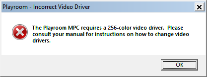
Installing The Playroom on a modern Windows 11 PC presents some challenges, as the game was designed for much older operating systems. To get it running, I used otvdm, a lightweight compatibility layer that allows 16-bit Windows applications to run on 64-bit Windows. Installation worked smoothly, but when I tried to launch the game, I encountered an error stating that The Playroom MPC requires a 256-color video driver.

Of course, Windows 11 supports far more than 256 colors, but the game’s outdated compatibility check prevented it from running.

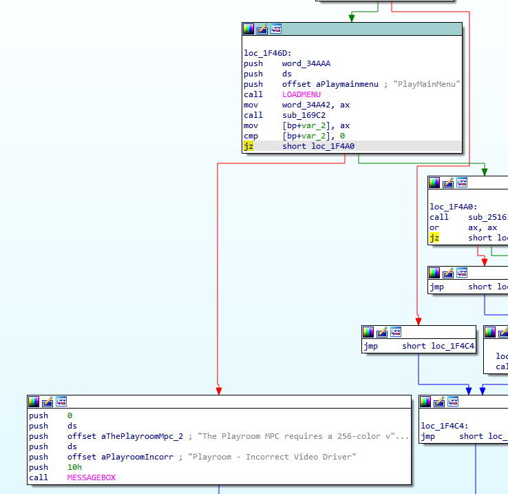
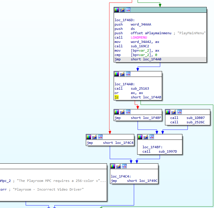
To bypass this limitation, I used IDA (Interactive Disassembler) to analyze the executable and locate the code responsible for the error message. I found a conditional jump instruction that triggered the message when the color depth check failed. By modifying just a single byte, I changed it to an unconditional jump, effectively skipping the check altogether.

In my version, I changed byte 0x285F9 from 74 to EB.

After this small patch, The Playroom launched successfully, proving that sometimes, a simple tweak can bring classic software back to life on modern hardware.

Before, with the check in place:

After, with the check patched out:

Playroom is now working on my Windows 11 machine.

Software alternative to removing the Golden Tee Sprint Modem

Golden Tee Live machines previously connected to the Internet/ITnet via a Sprint modem. The Sprint service was discontinued a few years ago. However, some older machines still have the modem soldered directly onto the I/O board. The modem attempts to connect to the Sprint towers during boot, but the connection is always unsuccessful. The result is a frustratingly long delay during startup as the game waits for a connection that will never happen.

The current solution has been to physically remove the modem by desoldering it from the I/O board. While effective, this approach comes with its own set of challenges. It requires disconnecting the I/O board and removing it from the machine, having soldering skills, and a fair amount of time to properly remove the component. For many, this can be a cumbersome process.

Fortunately, I’ve come up with an alternative solution that doesn’t require any soldering: a simple software fix that you can apply using just a thumb drive.

The Software Alternative: How It Works

Instead of physically removing the Sprint modem, we can trick the Golden Tee system into thinking the modem has already been removed. Golden Tee runs a Linux-based operating system, and one of the ways to disable the modem is by blacklisting the modem’s driver. By doing this, the game won’t try to load the Sprint modem driver during boot-up, and it will skip the long connection attempt to the now-defunct network.

I’ve created a script that you can load onto a USB thumb drive like an ordinary Golden Tee update. When you run the update, it adds the necessary “cp210x” (the modem driver) to the blacklist. This allows the system to boot more quickly, without waiting for the non-functional modem to connect.

Why You Should Consider This Solution

While desoldering the modem is a solution, it’s not always the easiest or safest option for the average arcade owner or operator. Removing a component from the I/O board requires a certain level of expertise with soldering equipment. Mistakes can easily lead to damaging the board, rendering the system unusable. For many users, this can be a daunting and risky task.

The software solution I’ve developed is a low-risk, hassle-free method that eliminates the need for soldering skills and disassembling the entire machine. It’s a much cleaner and safer solution that can be done in minutes with just a USB thumb drive and a few simple steps.

How to Create the USB Drive and Apply the Software Fix

Here’s how you can implement this solution in just a few easy steps:

1. Prepare Your USB Drive

First, you’ll need a USB thumb drive. It’s essential to format the drive as FAT32, which is the format that Golden Tee systems can read.

Steps to Format Your USB Drive in Windows:

  1. Plug the USB drive into your computer.
  2. Open File Explorer, right-click on your USB drive, and select Format.
  3. In the format window, make sure to select FAT32 as the file system. (If your drive is larger than 32GB, FAT32 might not appear. You can use a third-party tool to format it to FAT32.)
  4. Set the Allocation Unit Size to default (usually 4096 bytes).
  5. Click Start, then confirm that you want to proceed with formatting.

2. Download the Update Script

Next, you’ll need to download the update script.

  1. Download the update file to your computer.
  2. Once downloaded, copy the file to the root of your FAT32-formatted USB drive.
  3. Rename the file to update.bin

3. Load the Script onto Your Golden Tee Machine

Now that your USB drive is ready, it’s time to apply the update to your Golden Tee machine:

  1. Safely eject the USB drive from your computer and plug it into one of the USB ports on the Golden Tee machine.
  2. Power on the machine. The system should automatically detect the update file on the USB drive.
  3. The process will run automatically, and once it’s complete, the game will reboot.
  4. Remove the thumb drive.

4. Enjoy Faster Boot Times

Once the update is applied, your Golden Tee machine should boot much more quickly. The system will no longer wait for the non-functional modem to connect, and you’ll be able to jump straight into gameplay.